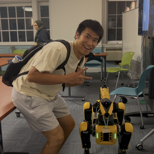
Jumbot-B: A 3D-Printed Bipedal Robot
By Zhenkai Gao & Xianmai (Chris) Liang
Course: ME 134 — Robotics Studio, Spring 2026, Tufts University
A 3D-printed bipedal robot built end-to-end: CAD, fabrication, electronics, and gait tuning. Jumbot-B walks at a best speed of 4 cm/sec using manually-tuned periodic gaits derived from servo encoder data.

Walking video → · Modular leg-swap demo → · All build & test footage (Drive folder) →
Overview
Jumbot-B is a small bipedal robot driven by eight servos and a Raspberry Pi, with chassis and feet 3D-printed in PLA. Each leg has hip pitch + hip yaw + hip roll plus a knee/leg joint — enough articulation to shift weight and twist the body during single-support phases of a gait.
We tuned gaits directly on the hardware using servo encoder feedback rather than running a simulation track.
Robot Specifications
| Spec | Value |
|---|---|
| Total weight | 15 lb |
| Height | 374 mm (~14.7 in) |
| Width | 230 mm (~9.1 in) |
| Length (depth) | 140 mm (~5.5 in) |
| Foot width | 122 mm |
| Walking speed (sustained max) | 0.5 in/sec (~1.27 cm/sec) |
| Walking speed (best) | 4 cm/sec |
| Walking terrain | Flat surface |
| Peak power draw | 9 V · 0.6 A · 5.4 W |
| Compute | Raspberry Pi 4 |
| Drive | 8 × LX-16A bus servos (position/velocity/temperature/voltage feedback) |
| Sensing | Onboard IMU + per-servo encoders |
| Material | PLA chassis & feet |
Robot Design & CAD
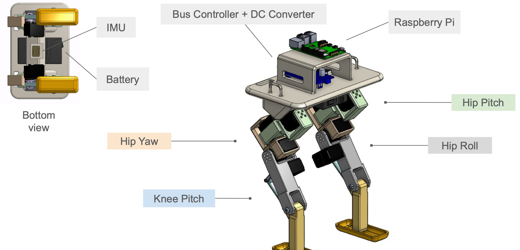 Key components: Raspberry Pi 4 compute on top, bus controller + DC converter on the platform, hip pitch / yaw / roll servos per leg, knee pitch servo, 3D-printed feet, and an IMU + battery on the underside.
Key design choices:
- DOFs (per leg): hip pitch + hip yaw + hip roll + knee/leg.
- Materials: PLA for the chassis and feet — rigid, predictable contact dynamics.
- Sensing: each servo reports position, velocity, temperature, and bus voltage; an onboard IMU provides body-frame orientation; encoder data drives the gait tuning loop.
- Compute: a Raspberry Pi 4 runs the gait controller and commands the servos over a half-duplex bus.
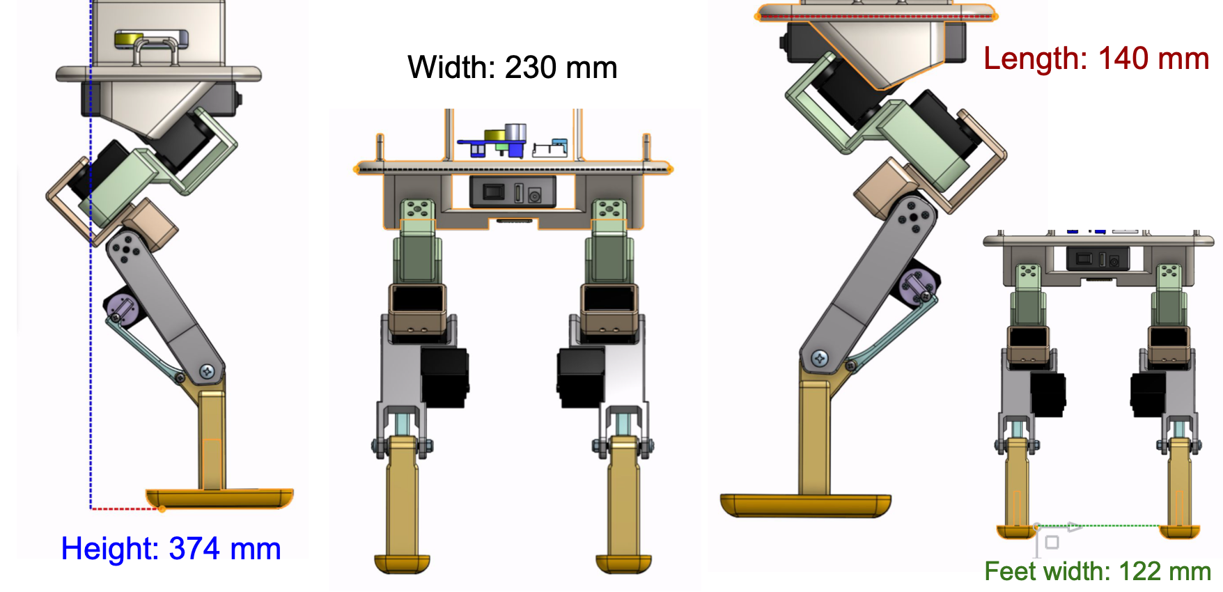 Main dimensions: 374 mm tall, 230 mm wide, 140 mm front-to-back, 122 mm foot stance.
Multi-pose CAD Views
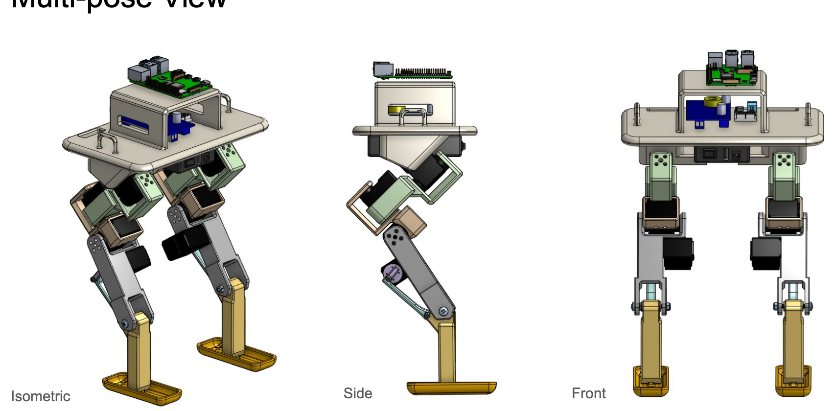 Isometric, side, and front views.
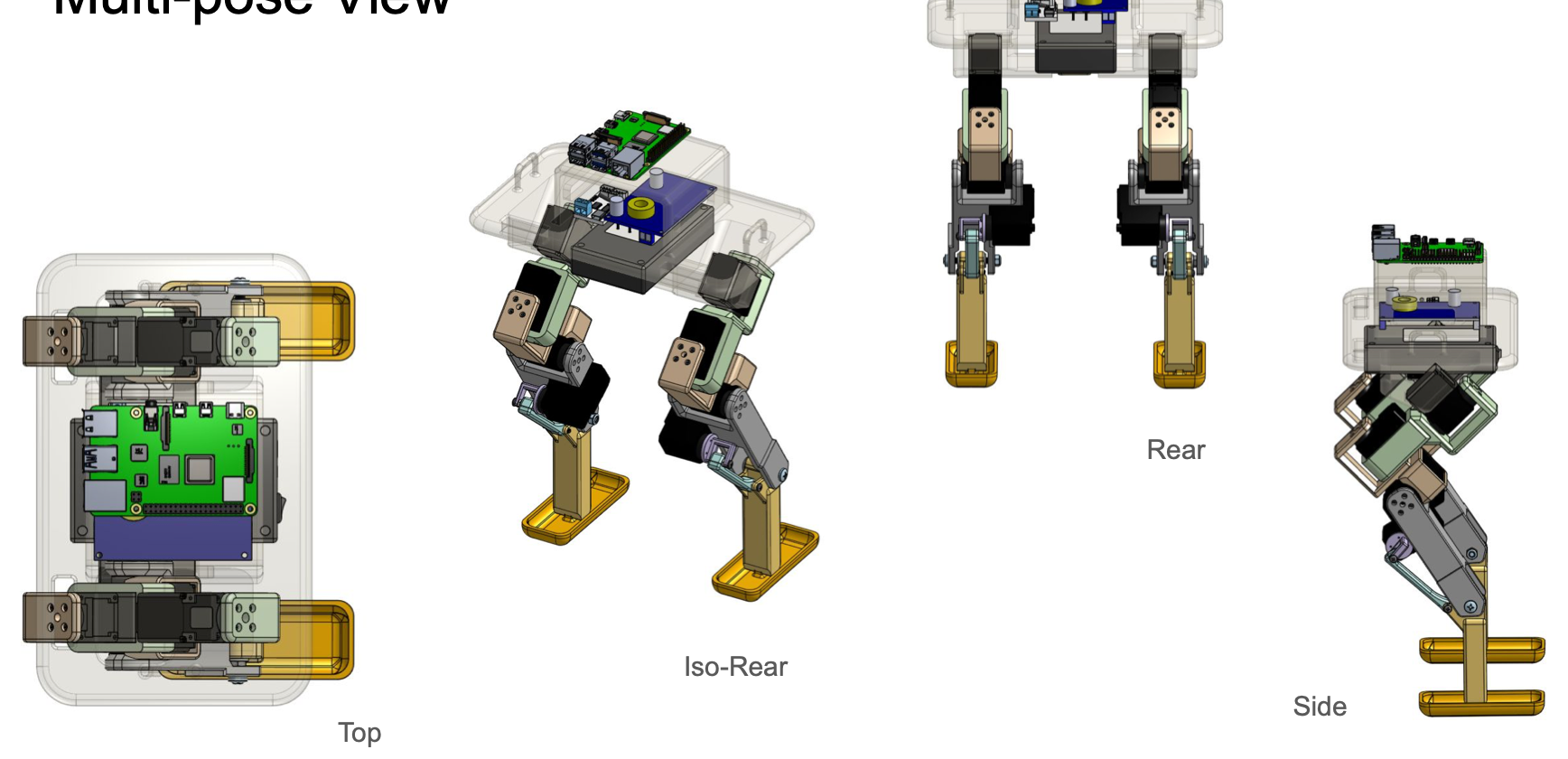 Top, iso-rear, rear, and side views — chassis shown semi-transparent so the internal electronics layout is visible.
Mechanical Assembly
The robot was built outward from a single-leg prototype: Onshape CAD → 3D-printed parts (PLA, Prusa MK4S for v1.0 prototyping, Prusa Core One for v2.0 final parts) → support-structure removal → assembly → single-leg motion test → tandem-leg test → full bipedal robot.
Single-leg motion test video →
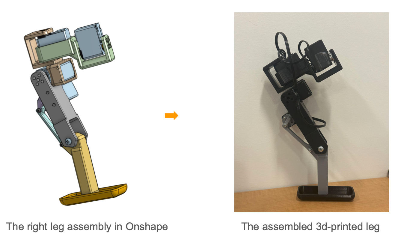 From CAD to real world — the right-leg assembly in Onshape (left) and the assembled 3D-printed leg with servos installed (right).
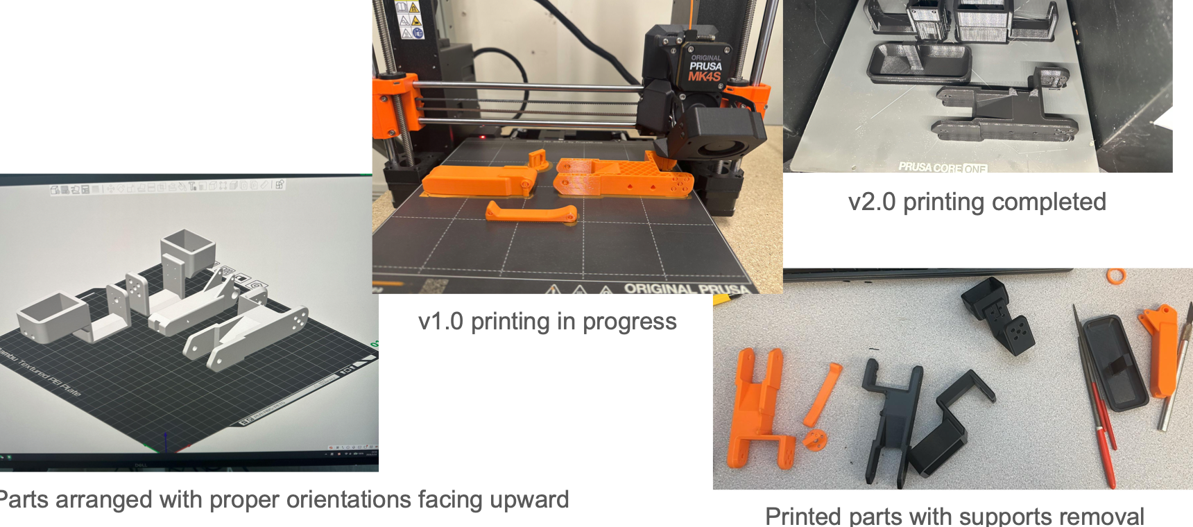 3D printing process — parts oriented in the slicer with overhangs facing up, v1.0 printing on a Prusa MK4S, v2.0 final parts on a Prusa Core One, and the printed parts with support structures cleaned off.
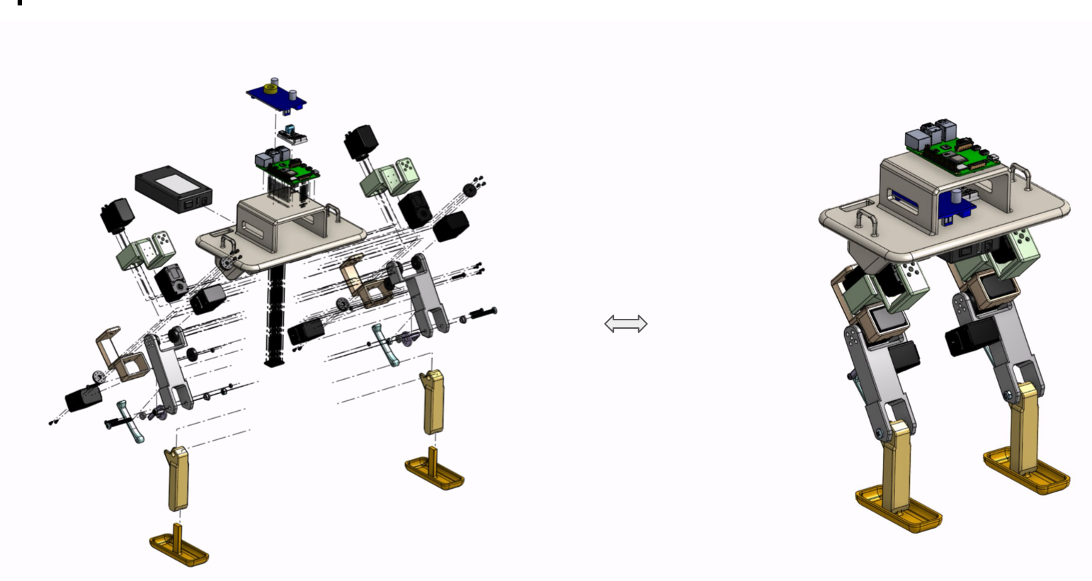 Exploded view of the full assembly — chassis plate, four servos per leg, linkage parts, hardware, and the foot module.
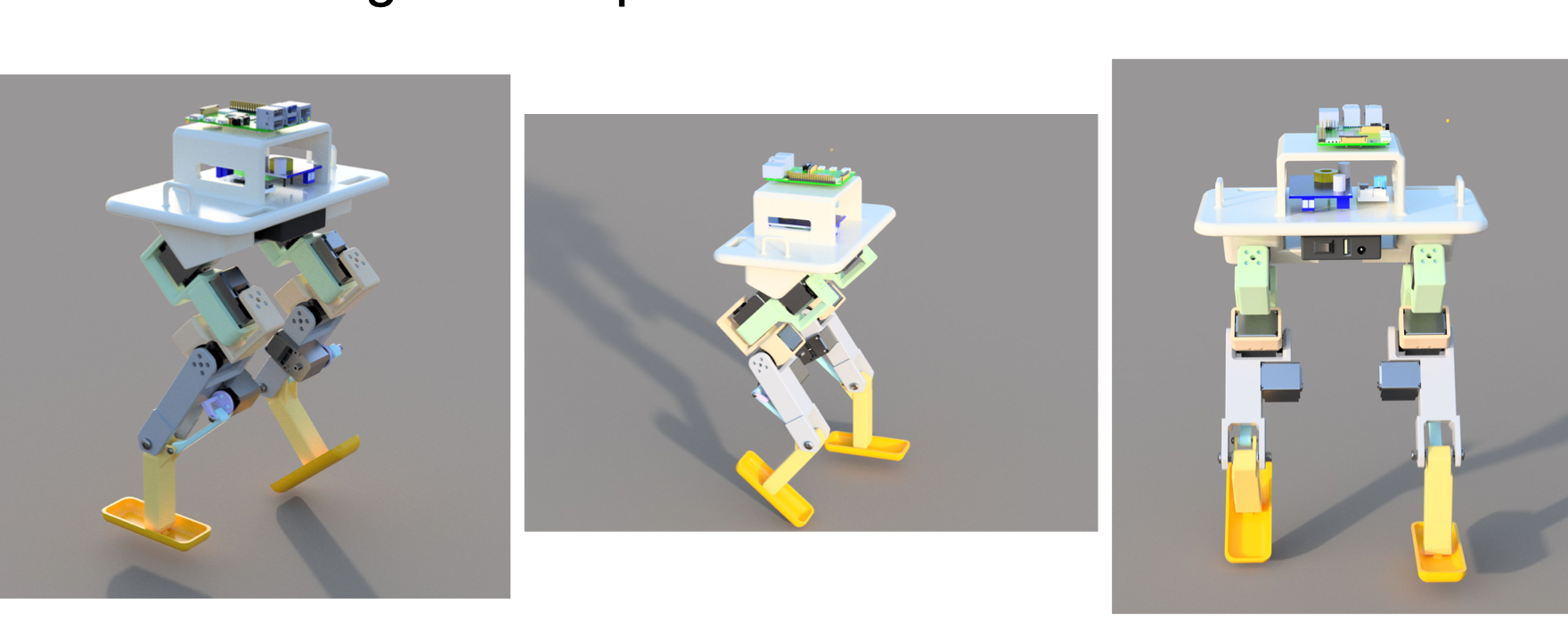 Three perspective renders of the assembled robot.
Assembled Robot Photos
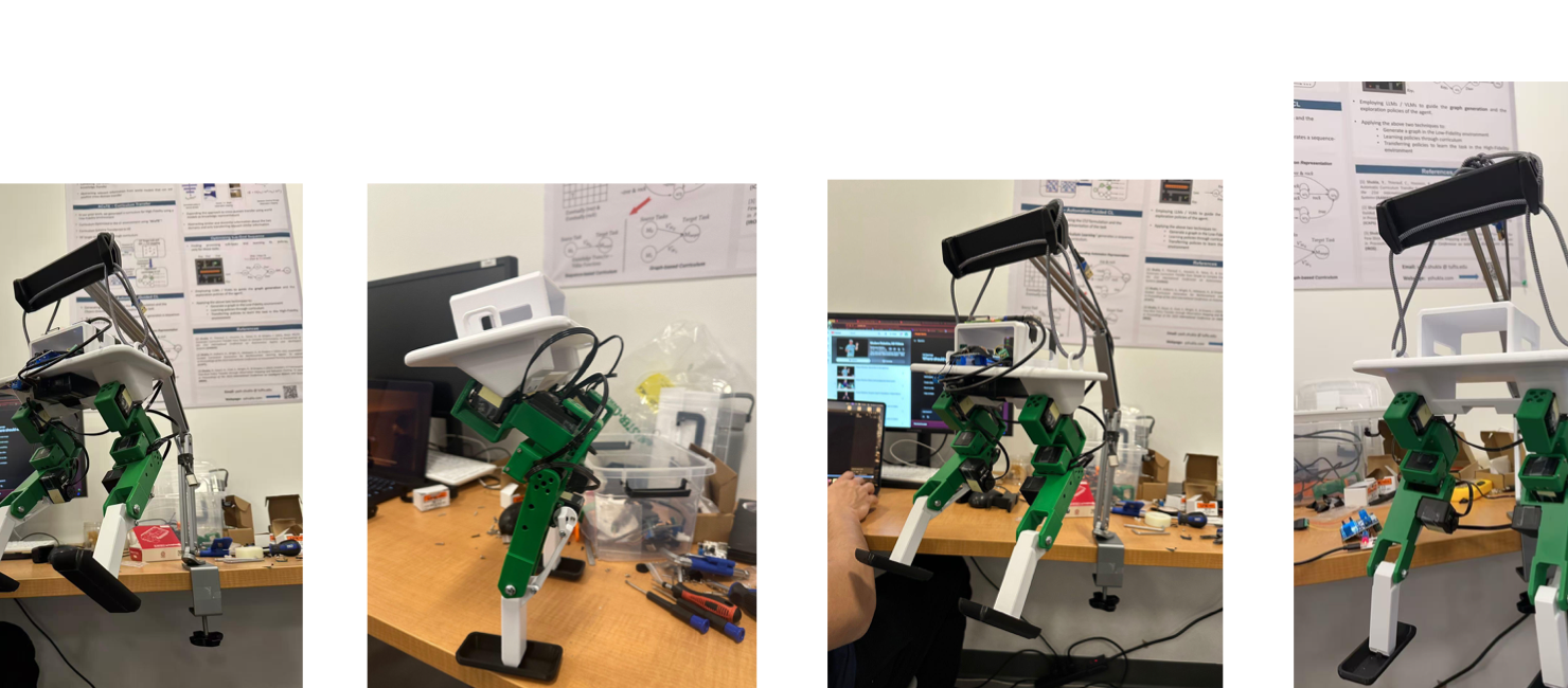 Painted/sanded final assembly on the bench — chassis bolted up, all 8 servos wired into the bus, cable bundle routed along the spine.
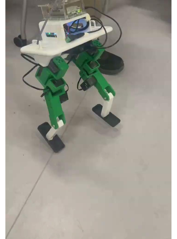 Behind the scenes: standing on the lab floor between gait-tuning runs.
Failure & Iteration Log
Issues found during the single-leg build phase and how each was resolved:
| # | Issue | Fix |
|---|---|---|
| 1 | Hip mount broke under small shear-bending loads | Increased wall thickness on the mount |
| 2 | Foot was too tight to assemble with the bottom leg link | Loosened tolerance for a clean fit |
| 3 | Servo disk broke during testing from motion conflict with the linkage | Fine-tuned the joint’s motion range to remove the interference |
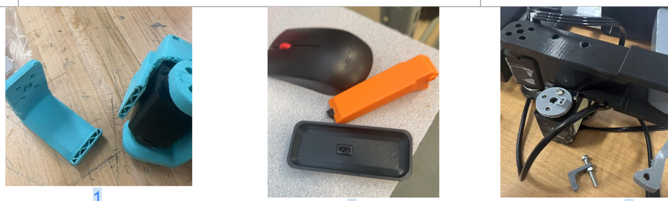 Failures captured at the hardware: (1) the cracked cyan hip mount split along the print layers under shear; (2) the original foot wouldn’t seat onto the bottom leg link — mouse for scale; (3) the snapped servo disk in-situ after the linkage drove it past its mechanical limit.
Bipedal-stage iterations (post-assembly):
- TPU foot experiment. We replaced PLA feet with TPU (85A) hoping for better ground compliance. The flexibility expanded the gait search problem — the robot lost static balance and was harder to control — and we reverted to PLA.
- Power delivery upgrade. The original thin wiring between the DC converter and battery produced enough voltage drop to make servo behavior inconsistent. Replacing it with thicker-gauge cables stabilized the power rail and gait reliability immediately improved.
- Cable routing. Wiring tidied and bundled along the chassis so legs can swing without snagging.
Hardware Implementation
The robot is controlled by a Raspberry Pi running a periodic gait function. Servo commands go out directly over GPIO; encoder positions are read back to record waypoints during tuning. Power comes from an onboard battery via a DC converter.
Walking video: Jumbot-B taking baby steps
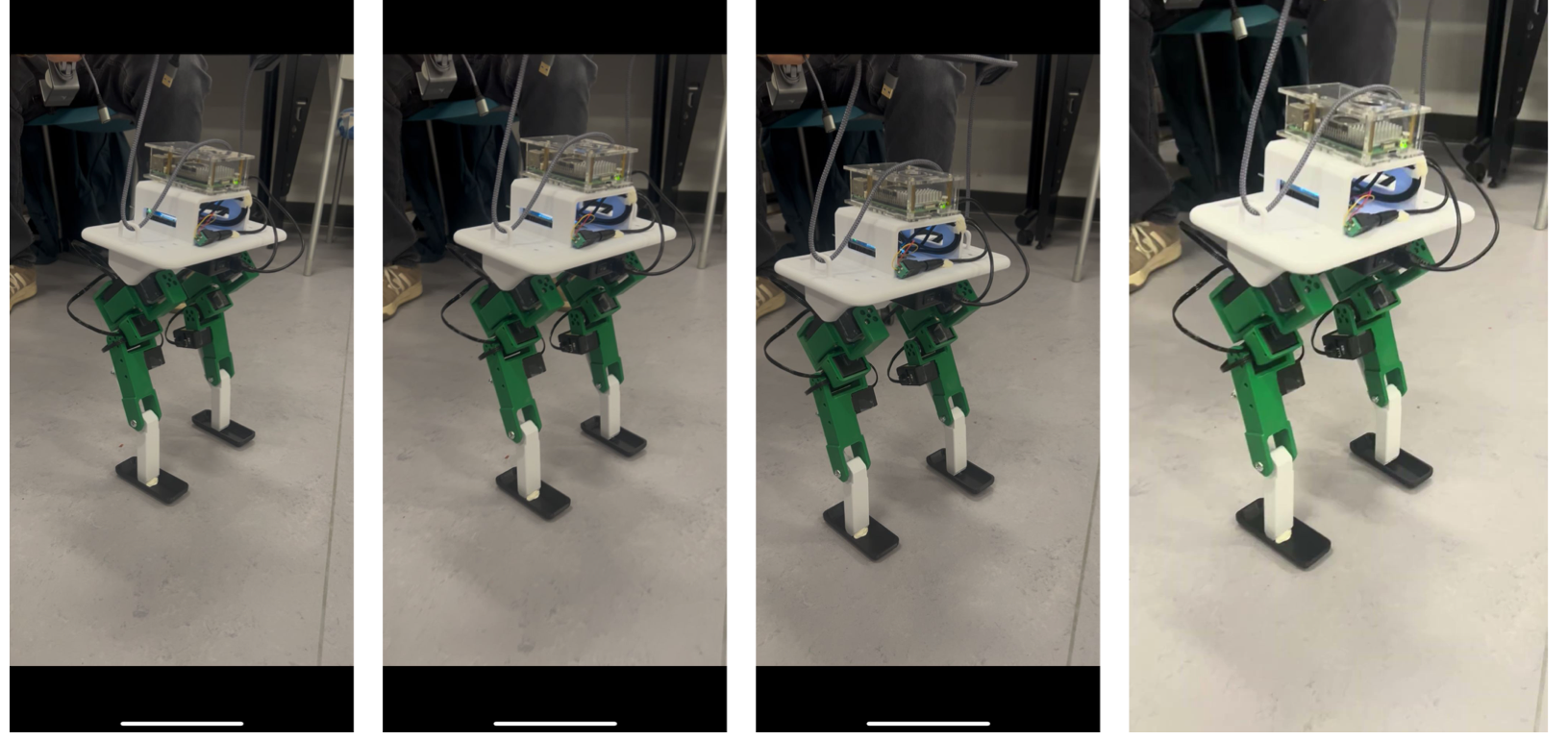 Frame sequence captured from the walking video — body shifts side-to-side as the swing leg clears the floor between consecutive support phases.
Hip Kinematics
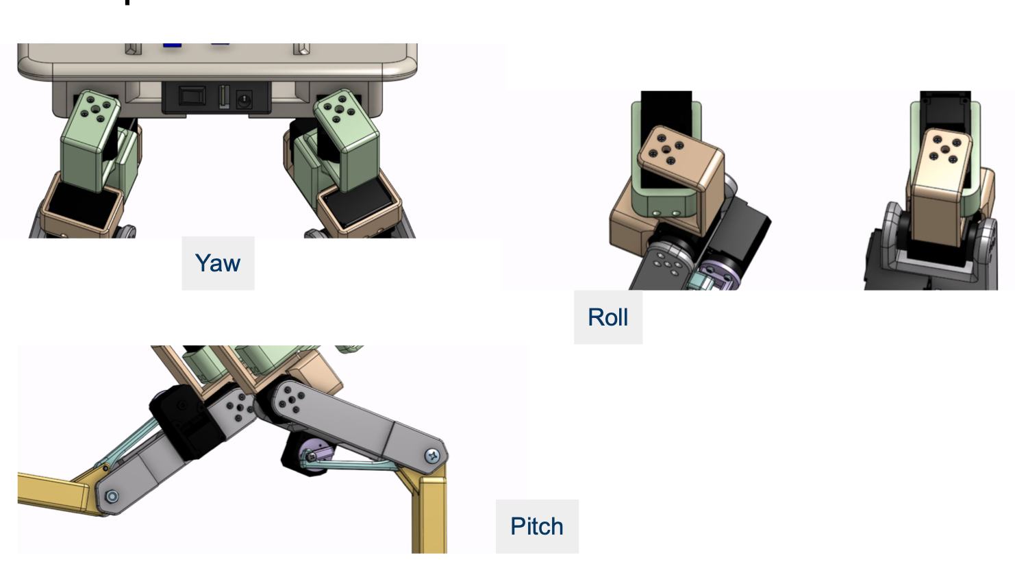 Three hip degrees of freedom — yaw, roll, and pitch — give Jumbot-B body-twisting capability for shifting weight during single-support phases of a gait.
Knee Linkage
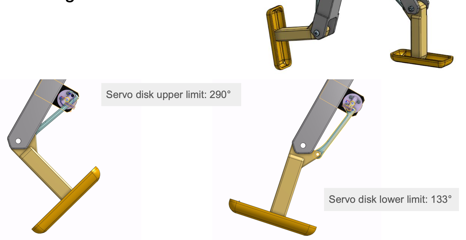 Four-bar knee linkage driven by the leg servo. Servo disk operating range: 133° (extended) to 290° (flexed). The mechanical limits were validated empirically by sweeping the servo through its full range and noting where the linkage starts to bind.
Servo Safety Limits
Per-joint position bounds, validated empirically by sweeping each servo through its full physical range and noting where the linkage starts to bind:
| Joint | Min (deg) | Max (deg) |
|---|---|---|
| Leg (knee) | 85 | 235 |
| Hip pitch | 95 | 190 |
| Hip yaw | 20 | 200 |
| Hip roll | 30 | 210 |
The gait controller clamps every servo command against these bounds so a misbehaving function can’t drive a servo into the chassis or fight the linkage.
Performance & Learning Curve
Speed measurements across iterations:
| Iteration | Speed (in/sec) | Speed (cm/sec) | Notes |
|---|---|---|---|
| Baby Steps — sustained max | 0.5 | 1.27 | First reliable walking gait |
| Baby Steps — fastest single cycle | 1.0 | 2.54 | 2 in/cycle, 2 sec/cycle |
| Final Performance | ~1.6 | 4.0 | After power-rail upgrade and gait re-tuning |
That’s roughly a 3.1× speedup from first walking gait to final, driven by hardware reliability fixes (thicker power wiring, cable management) and additional gait waypoint tuning.
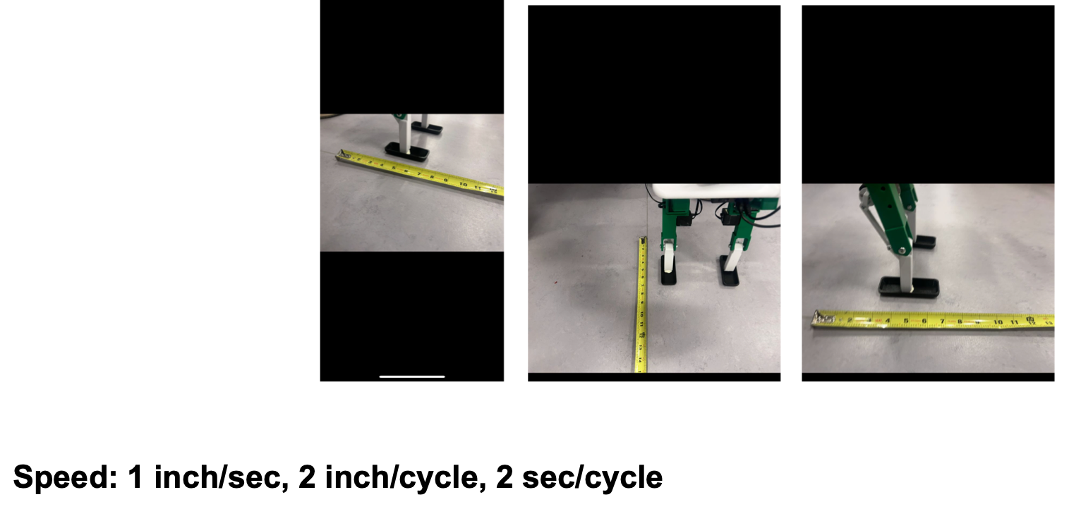 Speed measurement at the Baby Steps milestone — robot walking next to a tape measure: 1 in/sec at peak, 2 in/cycle, 2 sec/cycle.
Gait Development
Our approach to gait generation:
- Manually pose the robot through one walking cycle, capturing joint angles at each transitional state via the servo encoders.
- Use those waypoints to construct a periodic function for the joint trajectories.
- Iterate by hand, adjusting timing and amplitude until the robot walks stably.
The hip yaw + roll axes give Jumbot-B more body-twisting capability — useful for shifting the center of mass during single-support phases — but they also widen the gait search space, which is the main reason gait tuning has been the slow part of the project. Once roughly half a walking cycle is dialed in, the other half tends to mirror it.
Motor Data
We log per-servo position, velocity, temperature, and bus voltage during a walking cycle. The figure below covers an 8-second window across all 8 servos (Hip Pitch 1/2, Hip Yaw 1/2, Hip Roll 1/2, Leg 1/2):
- Position (deg): sinusoidal trajectories with leg/hip-pitch joints traversing the largest range; the periodic structure is exactly what the gait function commands.
- Velocity (deg/s): derivative of position; peaks near ±90 deg/s for the swing-leg joints.
- Temperature (°C): servos warm steadily from ~30 °C to ~40 °C over the run — comfortably below the failure window.
- Bus voltage (mV): ~8400–8800 mV with the upgraded wiring; pre-upgrade dips that caused jitter are no longer present.
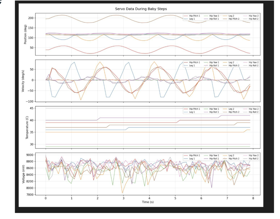 Servo data during the Baby Steps gait — 8 s of position, velocity, temperature, and bus voltage logged from all 8 servos.
Energy Efficiency
Quick efficiency numbers derived from the spec sheet and best-speed measurement:
| Metric | Value | How |
|---|---|---|
| Peak power draw | 5.4 W | 9 V × 0.6 A (measured) |
| Energy per meter at top speed | ~135 J/m | 5.4 W ÷ 0.04 m/s |
| Cost of Transport (CoT) | ~2.0 | P / (m · g · v) = 5.4 / (6.8 · 9.81 · 0.04) |
Cost of Transport is the standard dimensionless efficiency metric for legged locomotion. Humans walking sit around CoT ≈ 0.2; research quadrupeds like ANYmal land in the 1–3 range. Jumbot-B’s ~2.0 is in the right ballpark for a small experimental biped, though there’s clear room to optimize — most of the 5.4 W is going to support-leg holding torque, not forward motion.
Robot Reliability Routines
- Boot health check. Queries each servo for position, temperature, and bus voltage; aborts startup if any servo fails to respond or reports out-of-range temperature.
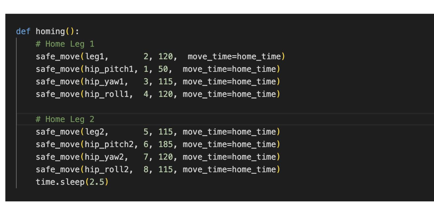
- Homing routine. Drives all 8 servos to a known stand-up pose via
safe_move, which clamps every commanded angle to the per-servo bounds before issuing the move. Used at startup and as a recovery pose between gait runs. - Servo-disconnect catch. The main control loop wraps servo commands in a
try/exceptforServoTimeoutError. If a motor disconnects or times out mid-gait, the loop logs a critical error and exits cleanly rather than charging on with a dead actuator. - Shutdown routine. Detorques servos, returns the robot to the home pose, then powers down — prevents the robot from collapsing under its own weight when killed mid-run.
 The
The homing() function: each leg’s four servos move to their home angle through a clamped safe_move wrapper, then a 2.5 s settle pause.
except ServoTimeoutError:
    print("\nCRITICAL ERROR: A motor disconnected or timed out!")
    print("Initiating emergency stop...")
    break
Lessons Learned
- Material choice has hidden second-order effects. TPU feet looked good on paper for compliance, but the flexibility blew up the gait problem and broke static balance.
- Power delivery is invisible until it isn’t. Thin wires produced enough voltage drop to make servo behavior inconsistent — symptoms looked like control bugs but were really hardware. Thick cables fixed it.
- Sim-to-real has a fixed setup cost. When that cost is high relative to the iteration budget — as it was once Onshape URDF export proved unreliable — tuning directly on hardware can dominate.
- Encoder-driven manual gaits work. The waypoint-based periodic function is crude but converges quickly once you find the first half of the cycle.
- Build quality before control quality. Three early single-leg failures (hip-mount cracking under shear, tight foot tolerances, servo-disk breakage from motion conflict) all came from CAD/print/assembly mismatches. Fixing each at the source — wall thickness, tolerance, motion-range checks — was much cheaper than working around them in software.
Future Work
- Refine the walking gait beyond the current 4 cm/sec.
- Land the Onshape → URDF pipeline so we can prototype gaits in MuJoCo before committing to hardware.
- Add new locomotion modes: turning, uneven terrain, jumping.
- Sweep a full power-vs-velocity efficiency curve to find the CoT-minimizing gait.
Bill of Materials
3D-printed structural parts (PLA except where noted) plus off-the-shelf hardware and electronics:
| # | Part | Qty | Source / Material |
|---|---|---|---|
| 1 | yallRoll_mount | 2 | 3D printed, PLA |
| 2 | rollPitch_mount | 2 | 3D printed, PLA |
| 3 | upper_left | 1 | 3D printed, PLA |
| 4 | upper_right | 1 | 3D printed, PLA |
| 5 | Leg_bottom | 2 | 3D printed, PLA |
| 6 | linkage_servo | 2 | 3D printed, PLA |
| 7 | knee_linkage | 2 | 3D printed, PLA |
| 8 | foot | 2 | 3D printed, PLA (TPU experiment reverted — see iteration log) |
| 9 | hip_mount | 1 | 3D printed, PLA |
| 10 | M5 pan-head Phillips screw | 2 | McMaster-Carr 92000A338 |
| 11 | M3 pan-head Phillips screw | 4 | McMaster-Carr 92000A128 |
| 12 | Phillips rounded-head thread-forming screw | 72 | McMaster-Carr 99461A921 |
| 13 | 8 mm OD dry-running nylon sleeve bearing | 4 | McMaster-Carr 6389K466 |
| 14 | M3 thin-profile hex nut | 4 | McMaster-Carr 90695A033 |
| 15 | M5 thin-profile nylon-insert locknut | 2 | McMaster-Carr 90453A113 |
| 16 | M5 thin-profile hex nut | 2 | McMaster-Carr 90695A037 |
| 17 | LX-16A bus servo motor | 8 | actuator |
| 18 | IMU | 1 | onboard sensor |
| 19 | Raspberry Pi 4 | 1 | compute |
| 20 | Servo bus controller | 1 | servo bus |
| 21 | DC converter | 1 | power |
| 22 | Battery | 1 | power |
| 23 | Wires & cables | — | wiring |
Code Repository
github.com/ChrisLiang33/jumbotB
Citations
[1] Sun, B., Mohamed Haris, S., & Ramli, R. (2026). A Systematic Review of Deep Reinforcement Learning for Legged Robot Locomotion. Instruments, 10(1), 8. https://www.mdpi.com/2410-390X/10/1/8
Acknowledgements
Built for ME 134 — Robotics Studio, Spring 2026 at Tufts University. Thanks to the course staff for the platform and feedback throughout the term.
Project by Zhenkai Gao and Xianmai (Chris) Liang.